I’ve worked on many different PLC logging projects over the years and have always needed to have a PLC available for testing. Then the other day I started thinking, I wonder if anyone has made PLC emulator software that I could just run on a Raspberry Pi? I always have spare Pis kicking around the office so this would be ideal. That is when I stumbled upon the OpenPLC project. It it exactly what I had been hoping for.
So I downloaded the latest version of Raspian Lite and copied it with dd onto an SD card.
sudo dd bs=4M if=2019-07-10-raspbian-buster-lite.img of=/dev/sdb conv=fsync
Then I created an empty text file named “ssh” in the boot partition of the SD card. This enables the SSH server to be enabled by default which is needed as this will be a headless set-up. Once the Pi was booted up and I SSH’d into it I performed all the usual steps such as extending the file system by typing “sudo raspi-config”, selecting “Advanced Options” and then “Expand Filesystem”. As well as changing the password of “pi” user, installing screen, performing a “sudo apt-get update” followed by a “sudo apt-get upgrade”. Setting a static IP address by opening “/etc/dhcpcd.conf” in nano and uncommenting the parts pertaining to static IP settings.
Next I just followed the steps on the getting started guide on the OpenPLC website. Which was just installing git
sudo apt-get install git
And then cloning the repo and running the install script
git clone https://github.com/thiagoralves/OpenPLC_v3.git
cd OpenPLC_v3
./install.sh rpi
After waiting for the installation to finish (it takes a while) I rebooted the Pi and opened a browser on my laptop to 192.168.1.10:8080 (where 192.168.1.10 was the static IP I set the Pi to earlier). The default username and password is openplc/openplc so once logged in make sure you update the password from within the Users menu option on the left-hand side of the web page.
The next step is to get the proper driver installed into OpenPLC. As I am running this on a Raspberry Pi B+ I navigated to the Hardware menu option, from the popup menu selected Raspberry Pi, clicked on Save changes and waited for a while the driver was installed.
And that was it. I now have OpenPLC running on a Pi in my server room. Pretty painless experience if you ask me.
The next step was to get the OpenPLC Editor installed so I could create the ladder logic program to run on my new OpenPLC device. They have a Linux version (yay!) but the install script is expecting an Ubuntu based OS, so I had to tweak the install script a bit to work on my Arch system. But again, no biggie.
Once the editor was installed I started to play around with creating my demo program and I started to run into some very weird errors when trying to preview the code in the editor. I narrowed the issue down to being caused when I was trying to set initial values to a register. For some reason this was creating my plc.st with incorrect formatting. For example, here is what my plc.st would look like if I set an initial value for FlagBit:
PROGRAM Modlog
  VAR
    TON0 : TON;
  END_VAR
  VAR
    FlagBit : INT     Counter : REAL;
    Data1 : REAL;
    Data2 : REAL;
    Data3 : REAL;
  END_VAR
  VAR
    MOVE6_ENO : BOOL;
    MOVE6_OUT : REAL;
    MOVE30_ENO : BOOL;
    MOVE30_OUT : REAL;
    MOVE38_ENO : BOOL;
    MOVE38_OUT : REAL;
    MOVE25_ENO : BOOL;
    MOVE25_OUT : INT;
  END_VAR
After doing some digging into the editor’s code (It is written in Python. Yay again!) I found and fixed the issue. I submitted the patch back to the author, but as of yet there has been no response.
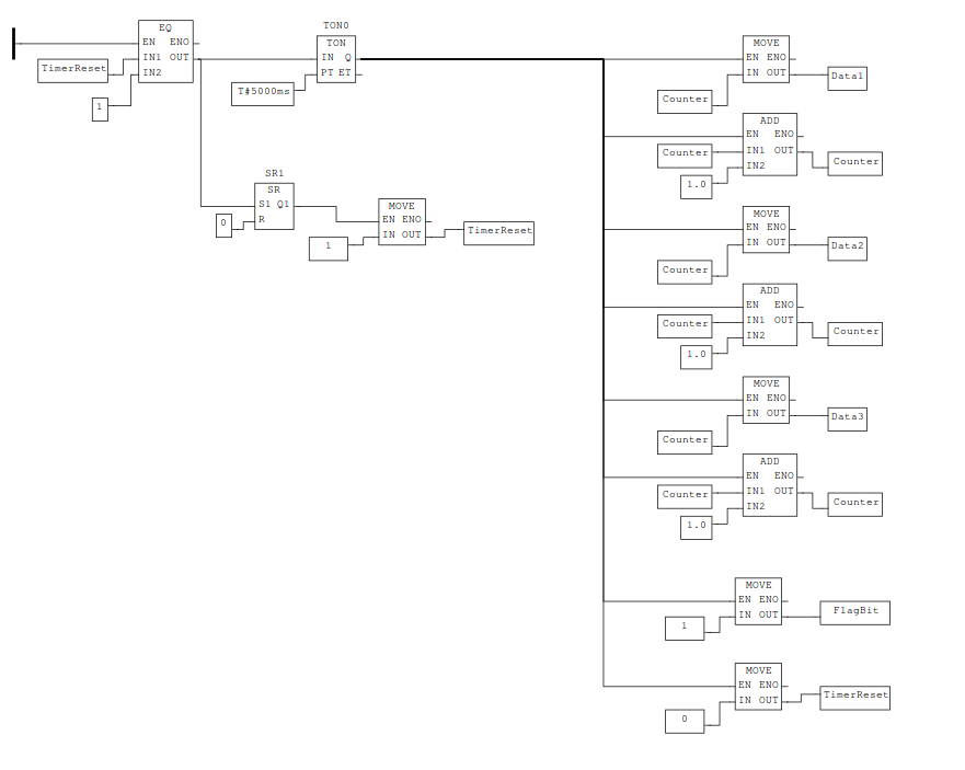
After applying the fix my very basic ladder logic program started to work. All it does is increment a counter every five seconds and puts those values into three registers. It then sets another register (the FlagBit) with a value of “1”. Then it waits and does it all over again. Simple, but works perfectly for my data logger testing needs.
Uploading the compiled ladder logic code was as easy as logging into the web portal for the Pi, selecting the compiled code file, and clicking to upload. Once OpenPLC was finished configuring the program I clicked the big “Start PLC” button and that was it.
For those interested, here is a screenshot of my super simple register filling ladder program
I will note that it did take me a bit to figure out the register mappings of OpenPLC so I thought I would share that here as well. You can find a table of the register mappings on this page https://www.openplcproject.com/scada.
So for 16 bit WORD registers you would set your register location in the OpenPLC editor to
%MW0,%MW1, etc and those would be accessible via ModBus at register1024,1025, etc.
For 32 bit DWORD registers you would set your register locations in the editor to
%MD0,%MD1, etc and those would each reference two registers starting at2048. So to read%MD0you would read register2048and2049.
Nothing crazy, but still took me some time to figure out.